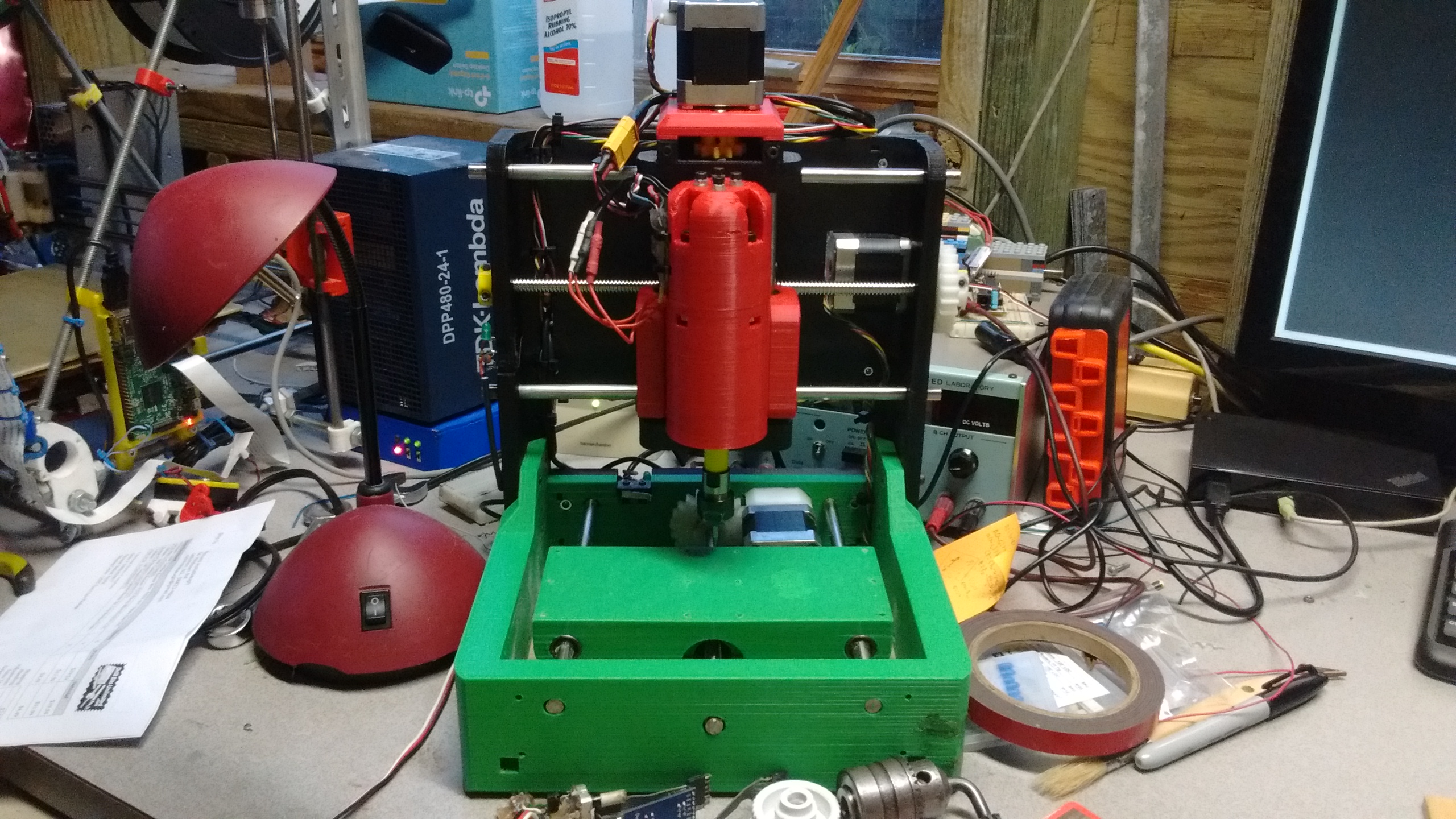
The Cyclone PCB Mill that I had build worked, but it had a few issues. Notably, the Z axis was only held down by gravity, causing it to not cut deep enough. The threaded rods were not perfectly straight, flexing the less than rigid frame as they turned, causing wobbly lines. In the end, I decided to design and print my own PCB mill, learning from the Cyclone. After months of design, days of 3d printing, and a week of assembly, I had a functioning PCB mill. The full CAD is available on Onshape.
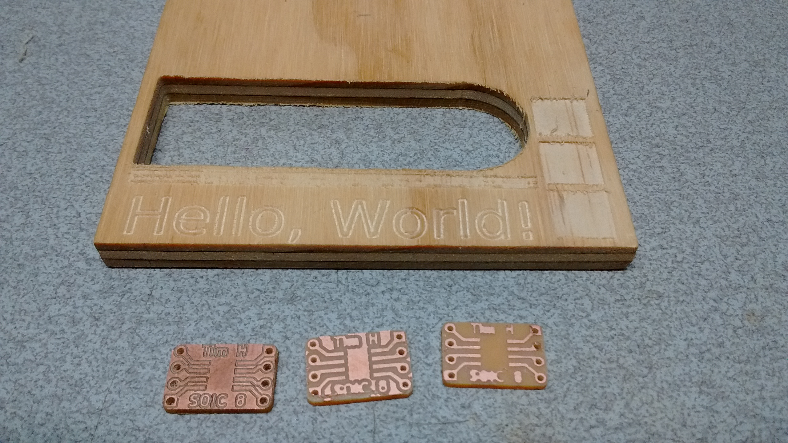
Here are some of the first tests:
still being mostly 3d printed. This meant there would need to be a lot more material in the frame. With the base being a full 20mm thick all around, and the back side 10mm, it is pretty chunky. Every load-bearing part is printed with 50% infill, which gives the whole thing a lot more heft to it than the Cyclone ever had.
In addition, I also tried to space the linear rods as far apart as possible. When forces are applied perpendicular to the linear rods, one of the rods effectively becomes a pivot point. By placing the other rod farther away, there ends up being less force applied to it, which reduces it's flex.
The combination of these approches meant that making the frame larger would make it stiffer. Ultimately, my 3d printer was the size constraint for the frame parts. Both the base and the back side used my the entire 200x200mm bed area, and even hung over a few mm. The base took the longest, at 30 hours of print time, and almost an entire spool of filament. Luckily, I haven't had to re-print it since!
Even though all this made it significantly better than the Cyclone, the frame is still not as stiff as a typical CNC machine. You can make it flex a bit by grabbing the spindle and wiggling. Most of the X axis flex comes from the cutout in the back side that allows the bed to stick out the back when it is all the way back. Here, it is only supported by the two 10mm thick sides of the back piece. On every other direction, most of the flex is in the linear rods, not the printed parts. This gives some confidence that it should be good enough.
Other than the frame, there are a few secondary goals. I wanted both the toolhead/spindle and the bed to be easily removeable, so I can swap them out. The toolhead is held in with four easily accessable M5 screws. This makes it easy to take the spindle off for work, or to install a pen mount to plot some pictures. The bed is held on by six M3 screws, that thread into nuts underneath.
Another improvement was to swap the threaded rods out for real lead screws. After a bit of use, I found that the nuts on the threaded rods would slowly chew themselves up, and leave metal debris everywhere. Also, threaded rods tend to not be particularly straight. Combined with the less-than-sturdy frame of the Cyclone, cuts could end up a bit wobbly. Using T8 lead screws fixed these: The delrin nuts don't grind themselves up, and they come pretty straight. I ended up with 2mm pitch instead of 8mm to try and minimize backlash from the gears, and to provide a bit more torque. They seem to be working pretty well.